20+ dc drive block diagram
The circuit diagram to. A 12V full-scale meter requires only 1 resistor and a single 3V to 15V supply in addition to the 10 display LEDs.

Pin On Electronics Knowledge
Inverters do the opposite of rectifiers which were originally large electromechanical devices converting AC to DC.
. FUNCTIONAL BLOCK DIAGRAM FEATURES Doubly Balanced Mixer. And both the converter and the motor interfaces by the power source to provide changeable voltage frequency and current to the motor. Similarly a DC voltage is stepped up or stepped down to desired voltage using such circuitry.
Signal-level determination down to 20 Hz. Single- or Dual-Supply Operation. This modulator can be used to control the op power of the supply.
E180 E200 E220 E250 E300 E350 E400 E500 E63 AMG 2009-2016. Priya Raghu Senior Hardware Engineer Microsoft Mark A. It uses an electronic controller to switch DC currents to the motor windings producing magnetic fields which effectively rotate in space and which the.
The power source in the above block diagram offers the necessary energy for the system. Low Distortion 24 dBm Third Order Intercept IP3 10 dBm 1 dB Compression Point Low LO Drive Required. 9 Block Diagram of AC Speed Control Motor System.
The LM3914 is very easy to apply as an analog meter circuit. First-generation model years 2005-2010 Chrysler 300 I was marketed as a four-door station wagon and sedan and in the second and present generation model years 2011 onwards it was marketed as a four-door sedanChrysler 300 - fuse box diagram Year of production. FUNCTIONAL BLOCK DIAGRAM VPOS INHI INLO COMM 3 8mA 10kΩ BAND GAP REFERENCE AND BIASING SIX 143dB 900MHz AMPLIFIER STAGES NINE DETECTOR CELLS SPACED 143dB INPUT-OFFSET COMPENSATION LOOP 2 2μA dB MIRROR 3kΩ 3kΩ 1kΩ COMM COMM COMM.
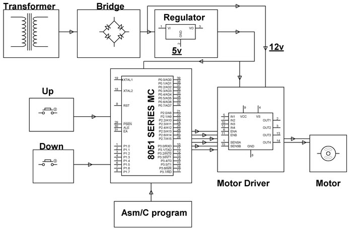
2010 2011 2012 2013 2014 2015. This means that it can control two DC motors at once. While another screw terminal block is for the Ground pin the 12V VCC for motor and a 5V pin however it can either be an input or output.
10 shows the waveforms of each block. Bandwidth 500 MHz RF and LO Input Bandwidths. Datacenter Secure Control Module Specification Authors.
250 MHz Differential Current IF Output DC to 200 MHz Single-Ended Voltage IF Output. Power Conversion Circuit with Drive Transformer. 53 Power Conversion Circuit with Drive Transformer.
The output of a 555 timer can drive a transistor-transistor logic TTL due to its high current output. A brushless DC electric motor BLDC motor or BL motor also known as an electronically commutated motor ECM or EC motor or synchronous DC motor is a synchronous motor using a direct current DC electric power supply. 10 Waveform for Each Block.
The speed set value d and the detected voltage e of the speed generated by a tacho-generator is compared in the comparison amplifier blockThen the level of the voltage signal a is determined. The simplified block diagram illustrates this extremely simple external circuitry. The input voltage output voltage and.
Valid for left-hand drive. Fuse box diagram fuse layout location and assignment of fuses and relays Mercedes-Benz E-Class W212. If the 1 resistor is a pot it becomes the LED brightness control.
The fuse block is located in the engine compartment on the left-hand side of the vehicle when viewed in the direction of travel. Shaw Principal Hardware Engineering Manager Microsoft Prakash Chauhan Server Architect Google Siamak Tavallaei Chief Systems Architect Google Mike Branch Server Architect Google Mason Possing Hardware Engineer Microsoft. Ⅵ Output Rectifier and Filter Circuit 61 Forward Rectifier Circuit.
Electric Drive Block Diagram Power Source. A complete tutorial of 555 Timer IC with its block diagram working of SENE 555 TimerPin Configuration and pin out diagram Download 555 data sheet. The Chrysler 300 I is a full-sized front-engine rear-wheel-drive luxury car manufactured by FCA US.
A DC to DC converter takes the voltage from a DC source and converts the voltage of supply into another DC voltage level. T2 is the drive transformer T1 is the switching transformer and TR1 is the current loop. They are used to increase or decrease the voltage level.
The resulting AC frequency obtained depends on the particular device employed. A power inverter inverter or invertor is a power electronic device or circuitry that changes direct current DC to alternating current AC. Fuse box diagram location and assignment of electrical fuses and relays for Toyota Prius XW30.
A 555 timer can also be used in dc-dc converters digital logic probes. The module can drive DC motors that have voltages between 5 and 12V with peak current up to 2A. True-decibel ac mode for multimeters.
The voltage signal a is low when the speed detected.
2
![]()
Pdf Hvdc Transmission Technology Review Market Trends And Future Outlook 2019 Abdulrahman Alassi 84 Citations
Dc Motor Speed Control Best And Crucial Controlling Methods
Block Diagram Of Dc Motor Speed Controls Using Thyristor Download Scientific Diagram
Dc Motor Speed Control Best And Crucial Controlling Methods

Pin On Electronique

Block Diagram Of Dc Motor Drive Download Scientific Diagram
Dc Generator Block Diagram Download Scientific Diagram

Circuit Diagram Of The Constant Speed Dc Motor Driver D In Figure 4 Download High Resolution Scientific Diagram
![]()
Reduced Block Diagram Of Dc Motor With Constant Field Current Hence The Download Scientific Diagram
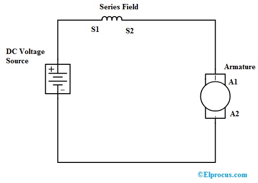
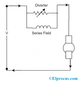
Dc Series Motor Circuit Diagram Characteristics And Its Applications

Block Diagram Of A Single Motor Drive System With Different Dc Side Download Scientific Diagram

Block Diagram Of Dc Drive Download Scientific Diagram
Dc Motor Speed Control Best And Crucial Controlling Methods
Dc Motor Speed Control Best And Crucial Controlling Methods

Block Diagram Of Dc Motor Download Scientific Diagram

Pdf Hvdc Transmission Technology Review Market Trends And Future Outlook 2019 Abdulrahman Alassi 84 Citations